Wave soldering and hand soldering are two methods which are widely used for joining electronic components, but they are suited to different production requirements. Wave soldering is intended for the efficient and repeated soldering of appropriate printed circuit board assemblies, whereas hand soldering is generally employed for prototypes, repairs, rework and for certain manual assembly operations.
The choice of solder wire when carrying out hand soldering and the choice of solder material for wave soldering are related yet distinct decisions; by understanding this difference engineers and procurement teams will be able to select materials appropriate to the process rather than supposing that one solder product will suit every application.
What Is the Difference Between Wave Soldering and Hand Soldering?
Wave soldering involves the use of a regulated wave of molten solder to form both electrical and mechanical connections on appropriate PCB assemblies, typically when the boards are moving along an automated production line.
Hand soldering, on the other hand, makes use of a soldering iron which is manually controlled and usually involves the use of solder wire in order to create or repair individual joints. The key differences lie in the production volume, the degree of process control, the equipment employed, the method of material delivery and the suitability for the assembly.
Wave soldering vs hand soldering: comparison table
| Comparison factor | Wave soldering | Hand soldering |
| Basic method | PCB passes over a wave of molten solder | A heated soldering iron transfers heat to the joint |
| Solder delivery | Solder bath or pot | Commonly solder wire |
| Typical use | Suitable through-hole PCB production and selected mixed-technology assemblies | Prototypes, repairs, rework and manual assembly |
| Production volume | Well suited to repeatable production runs | Well suited to low volumes and individual joints |
| Process control | Machine settings and line parameters | Operator technique and controlled tool settings |
| Flux application | Commonly applied separately before the solder wave | May be supplied in flux-cored wire or applied separately |
| Main material considerations | Bath alloy, contamination control, flux and process compatibility | Alloy, wire diameter, flux type and application requirements |
| Key limitation | Requires appropriate equipment, setup and board compatibility | Labour-intensive for large numbers of joints |
Neither method is universally better. The correct choice depends on the PCB design, component technology, required throughput, quality requirements and available production equipment.
How Does Wave Soldering Work?
Wave soldering produces the joints by bringing the appropriate PCB soldering surfaces into contact with a wave of molten solder under controlled conditions. The assemblies usually go through the steps of applying flux, preheating and then soldering, followed by cooling and inspection. This method is generally used in the case of through-hole components and on certain mixed-technology boards, but only if the board design and the components are appropriate for the machinery.
The typical process involves:
- Flux application: A suitable flux prepares the surfaces for soldering by helping remove or manage oxides.
- Preheating: The assembly is heated to support the soldering process and manage thermal conditions.
- Solder wave contact: The underside of the board contacts molten solder to form the required joints.
- Cooling: The assembly cools under controlled conditions.
- Inspection: Joints are checked against the applicable assembly requirements.
Wave soldering generally does not use solder wire as its primary feed material during production. Instead, the solder alloy is maintained in a bath, and the process depends on bath composition, temperature, flux, conveyor settings, board design and other controls.
How Does Hand Soldering Work?
When hand soldering, a heated soldering iron is used to supply energy to the joint so that the solder can wet the right surfaces and make a connection. The operator usually feeds solder wire into the joint once the necessary temperature and wetting conditions have been reached. Reliable results are based on the choice of alloy, the effectiveness of the flux, the condition of the tip, temperature control, the design of the joint and the operator’s technique.
The typical steps are:
- Select the appropriate solder alloy and wire diameter.
- Confirm that the flux system suits the application and component requirements.
- Prepare the joint and soldering tool according to the approved procedure.
- Apply heat to the joint and feed solder wire in a controlled manner.
- Allow the joint to solidify without disturbance.
- Inspect the result against the applicable acceptance criteria.
Hand soldering is useful when access, flexibility or individual-joint control matters more than automated throughput. It is also commonly used for prototype development, repair and rework, provided the work follows the required procedures and avoids thermal damage.
Which Solder Material Is Used for Wave Soldering?
Wave soldering normally uses a solder alloy held in a bath rather than conventional solder wire fed directly to each joint. The alloy must match the assembly specification, component finishes, process requirements and any applicable regulatory or customer restrictions. The solder bath also requires monitoring because alloy composition can change through contamination or process-related metal dissolution.
The selection of solder wire material for related hand-soldering operations should be evaluated separately from the solder alloy used in the wave bath, as each process has different material-delivery and flux requirements.
When selecting solder material for wave soldering, evaluate:
- Alloy composition: Confirm the specified alloy and permitted composition limits.
- Melting and process temperature: Ensure compatibility with the assembly and manufacturing process.
- Bath control: Establish requirements for monitoring composition, contamination and operating conditions.
- Flux compatibility: Use a flux system approved for the alloy, board and process.
- Standards and customer requirements: Follow the applicable assembly specification and contract.
- Regulatory requirements: Verify relevant restrictions and exemptions for the finished product.
Lead-free alloys and lead-containing alloys have different process characteristics. Neither should be selected solely because it is described as modern, economical or easy to use. The assembly specification and validated process determine the appropriate choice.
Which Solder Wire Is Suitable for Hand Soldering?
The choice of solder wire appropriate for hand soldering will depend on the alloy, the type of flux, the diameter of the wire, the size of the joint, the sensitivity of the component, and the soldering procedure that is required; in the case of fine-pitch electronics a smaller diameter may be necessary for controlled feeding, while in other cases larger terminals will need a different size and the wire must also satisfy the material and quality requirements applicable to the final assembly.
When comparing best solder wire manufacturers, buyers should also review the available alloy options, flux specifications, wire diameters and technical documentation to ensure the product meets their application requirements.
Consider these factors before choosing solder wire:
- Alloy: Use the alloy specified for the application and manufacturing process.
- Flux core: Select a suitable flux system for the surface condition and residue requirements.
- Wire diameter: Match the amount of solder delivered to the joint size and operator technique.
- Thermal sensitivity: Follow component and PCB limits to reduce the risk of overheating.
- Residue requirements: Confirm whether cleaning is required and whether the flux residue is acceptable for the application.
- Documentation: Check the material specification and relevant technical documents.
- Wire construction: Depending on the application, compare flux-cored solder wire with solid solder wire, which does not contain an internal flux core and may require separately applied flux.
For a broader selection framework, see the internal solder wire buying guide. It should remain the main article for general solder-wire selection, while this article focuses on differences between wave and hand soldering.
Can the Same Solder Alloy Be Used for Wave and Hand Soldering?
The same alloy designation may be used in both wave soldering and hand soldering, but this does not imply that the entire solder material or process is interchangeable. In wave soldering a molten bath is maintained, while hand soldering wire is usually used which may have a flux core. There are differences between the methods in terms of flux delivery, contamination control, process temperature and the equipment required.
Before using the same alloy in both processes, confirm:
- The alloy composition is approved for both applications.
- The flux system is appropriate for each process.
- The soldering temperatures and process windows are validated.
- The component and PCB requirements are met.
- The material meets customer and regulatory specifications.
- The finished joints meet the required acceptance criteria.
For example, an alloy selected for hand soldering may be available as flux-cored wire, while the wave process uses compatible alloy in a solder bath with a separately controlled flux application. The alloy designation alone does not establish that the entire process setup can be transferred unchanged.
Wave Soldering vs Hand Soldering: Which Process Should You Choose?
Wave soldering is usually appropriate in cases where a production line has to repeatedly solder many compatible joints on PCBs, whereas hand soldering is generally more practical when dealing with prototypes, individual joints, repair or rework. When making your decision you should take into account the board design, the component technology, the output volume, the quality requirements, the availability of equipment and the total production cost rather than basing it solely on speed.
Use this practical guide:
| Requirement | Usually worth evaluating |
| High-volume production of compatible through-hole assemblies | Wave soldering |
| Prototype or low-volume assembly | Hand soldering |
| Individual repair or rework | Hand soldering with an approved procedure |
| Large numbers of consistent joints | Wave soldering, if the board is suitable |
| Mixed-technology PCB | Process depends on component placement and assembly design |
| Specialised or heat-sensitive components | Evaluate the complete thermal process and component limits |
Wave soldering is not automatically the best option for every high-volume board. Some designs are better suited to selective soldering or other automated processes. Likewise, hand soldering should not be assumed to deliver acceptable quality without suitable tools, trained operators and documented procedures.
How Do Flux Type and Solder Wire Diameter Affect the Choice?
The flux and solder used should be appropriate for the soldering process and the type of joint being made. In the case of hand soldering, flux-cored solder wire is commonly used so that the flux is released as the wire melts. With wave soldering, the flux is applied separately prior to the printed circuit board coming into contact with the solder wave. It is therefore especially important to consider the diameter of the wire when manual feeding is involved, whereas wave soldering depends on the bath and process controls.
For hand soldering, consider:
- The amount of solder needed for the joint.
- The wire diameter that allows controlled feeding.
- The flux chemistry and residue requirements.
- The alloy’s compatibility with the assembly.
When it comes to wave soldering, attention should be paid to the flux applied separately, the solder-bath alloy, the condition of the bath, the preheating procedure and the machine settings. A flux that is appropriate for hand soldering should not be taken as automatically being suitable for use in a wave soldering process. Selection should be based on the manufacturer’s instructions for the flux and on the approved process specification.
How Can You Prevent Common Soldering Defects in Both Processes?
To prevent soldering defects it is necessary to control the quality of the material, the condition of the surface, the temperature, the application of the flux, the geometry of the joint and the process settings. In the case of wave soldering bridging, insufficient solder or poor wetting may occur, while hand soldering may result in cold joints, excess solder or disturbed joints. Since these problems can have various possible causes, the diagnosis should take into account both the process and the inspection evidence.
Practical controls include:
- Use approved solder alloys and compatible flux.
- Keep soldering surfaces clean and follow the specified preparation procedure.
- Control preheating and soldering temperatures within the validated process window.
- Maintain suitable tools, soldering tips and production equipment.
- Follow the approved procedure for the board and component design.
- Inspect finished joints against the applicable acceptance criteria.
- Record recurring defects and investigate their root causes rather than repeatedly correcting symptoms.
A defect should not automatically be attributed to the solder wire. Equipment condition, component finishes, PCB design, contamination and process settings may also contribute.
What Quality Standards and Documentation Should You Check?
The soldering quality must be assessed in accordance with the relevant standards, customer requirements and the approved procedures for the assembly; IPC J-STD-001 covers the requirements for soldered electrical and electronic assemblies and IPC-A-610 gives the criteria for judging the acceptability of electronic assemblies, the specific class, revision and contractual requirements deciding which criteria are to be applied.
Before approving a material or process, verify:
- The specified alloy and material requirements.
- The approved flux and process conditions.
- Applicable customer and regulatory requirements.
- The relevant edition of the assembly and acceptance standards.
- Required material certificates and traceability.
- Inspection and corrective-action procedures.
Useful references include the IPC document revision table and IPC standards information. Always verify the current applicable revision and use the complete standard rather than relying on a summary to determine acceptance.
How Kothari Metsol Fits into Solder Material Selection
The different types of soldering materials offered by Kothari Metsol should be assessed in relation to the specific alloy, wire form, flux and technical specifications required for a given application. Before placing an order, buyers must check the available product variants, the material documentation and the intended uses. When deciding between wave soldering and hand soldering, the choice should first be based on the production process and then a compatible material should be selected.
When carrying out hand soldering, check the product information relating to the solder wire and make sure that the available alloy, diameter and flux options are suitable. In the case of wave soldering, it is necessary to confirm that both the alloy of the solder bath and the flux applied separately comply with the approved process requirements. Suitability of the product should be checked based on the current specifications rather than being deduced from a general product description.
Which Solder for Which Process?
In the case of wave soldering a controlled amount of molten solder alloy is used, whereas with hand soldering solder wire is applied using a soldering iron. The choice of material will depend on the assembly process, the requirements regarding the alloy, compatibility with the flux, the design of the components and the quality standards. When it comes to production, the entire soldering process should be verified rather than selecting a material simply on the basis of its price or the name of the alloy.
| Application or requirement | Typical material or process choice | What to verify |
| High-volume through-hole PCB assembly | Wave soldering with a compatible solder-pot alloy | Alloy specification, pot condition and process settings |
| Prototype assembly or low production volume | Hand soldering with suitable solder wire | Alloy, wire diameter and flux type |
| PCB rework and component replacement | Hand soldering with application-appropriate solder wire | Thermal sensitivity, joint access and repair procedure |
| Mixed-technology PCB | Wave soldering for suitable through-hole joints, followed by selective hand work where required | Component clearance, masking, thermal exposure and sequence |
| Lead-free electronics production | Lead-free alloy compatible with the product specification | Customer requirements, applicable regulations and process validation |
| Maintenance or repair of legacy equipment | Specified alloy or an approved alternative | Existing alloy, compatibility and repair requirements |
The important distinction is that wave soldering uses solder in a pot, whereas hand soldering typically uses solder wire. A material suitable for one process is not automatically suitable for the other. Always confirm the alloy, flux system, equipment settings and acceptance criteria before production.
Managing the Wave Solder Pot
In order to ensure reliable joints, a wave solder pot must have a controlled temperature, a stable alloy composition, consistent solder levels and undergo regular maintenance. The operators have to follow the process instructions which have been validated, record any additions of material and check for the formation of dross. If the temperature is raised or more solder is added without first investigating the cause of the process problem, material losses will increase even though the fundamental issue remains uncorrected.
What should be monitored in a wave solder pot?
A wave solder machine uses molten solder to form joints on suitable PCB assemblies. The bath must remain within the alloy supplier’s recommended operating range and the equipment manufacturer’s instructions.
Key controls include:
- Solder alloy: Confirm the alloy matches the approved process specification. Do not mix alloys casually, as this can change bath composition and joint performance.
- Pot temperature: Use the qualified setpoint and verify actual temperature with calibrated equipment. Avoid increasing it simply to compensate for poor wetting.
- Solder level: Maintain the specified level to support stable wave formation and consistent contact with the assembly.
- Dross formation: Dross consists largely of oxides that form at the molten solder surface. Record its formation and removal to help identify changes in process conditions.
- Wave height and stability: Check that the wave remains within the machine’s validated operating window.
- Contamination and alloy analysis: Follow the maintenance schedule and test the bath when required by the process specification or supplier guidance.
How can manufacturers reduce solder waste?
Solder losses may result from the removal of dross, material being carried away by the assemblies, spillage and the need for unnecessary replacement of the alloy. Waste which is unnecessary can be reduced by improved monitoring, careful handling and the maintenance of consistent operating conditions.
You should not regard all dross as being suitable for recovery and reuse, and used recovered material must not be returned to the bath unless there is an approved procedure. It is necessary to follow the maintenance instructions provided by the equipment supplier as well as the recommendations from the solder supplier concerning alloy control and disposal. Furthermore, trends in dross can also help to identify process changes that merit investigation.
Wave solder pot maintenance checklist
- Record actual bath temperature and compare it with the approved setpoint.
- Check solder level and wave stability at the specified intervals.
- Inspect the pot, pump, nozzles and relevant machine components according to the maintenance schedule.
- Record solder additions, alloy batches and any available composition test results.
- Track dross generation and removal.
- Investigate repeated wetting problems, bridging or inconsistent joints before changing multiple process variables.
- Keep maintenance records available for quality review.
Cost Comparison and Break-Even in ₹
Wave soldering becomes more economical as the volume of production rises so that the costs of the equipment, setup and maintenance can be distributed among a large number of boards. Although hand soldering usually involves a smaller initial outlay it does so at the expense of more operator time for each joint. The true break-even point is determined by labour rates, throughput, board design, changeovers, defect rates, consumables and equipment ownership costs, not merely by the cost of solder per kilogram.
Wave soldering vs hand soldering: cost factors
| Cost factor | Wave soldering | Hand soldering |
| Initial investment | Higher: machine, installation and supporting equipment | Lower: irons, stations and basic tools |
| Labour | Often lower per board at stable production volumes | Can be higher per board because work is manual |
| Setup and changeover | May require preparation, parameter checks and line setup | Usually simpler for small batches or varied tasks |
| Solder consumption | Depends on bath management, dross, drag-out and process conditions | Depends on wire diameter, joint size, operator technique and rework |
| Maintenance | Pot, pump, conveyor and related machine maintenance | Iron tips, heating elements and station maintenance |
| Quality inspection | Process monitoring plus inspection and testing | Operator technique, inspection and testing |
| Best cost opportunity | Repeatable, suitable high-volume production | Prototypes, repair, small batches and targeted rework |
How to calculate the cost per board
Use the following practical model to compare both processes using your own production data.
Wave soldering cost per board

Hand soldering cost per board

Include setup time, changeovers, consumables, inspection and scrap in the comparison. If a process produces more defects, its apparent material savings may disappear once rework and rejected boards are counted.
Illustrative example in Indian rupees
The following figures are hypothetical examples, not Kothari Metsol prices or industry benchmarks. Replace them with actual costs from your plant before making an investment decision.
| Cost item | Wave soldering | Hand soldering |
| Allocated equipment, setup and maintenance per batch | ₹8,000 | ₹1,000 |
| Labour and production cost per board | ₹12 | ₹45 |
| Solder and other process consumables per board | ₹8 | ₹10 |
| Total variable cost per board | ₹20 | ₹55 |
Under these assumptions:
- Wave soldering batch cost = ₹8,000 + (₹20 × number of boards).
- Hand soldering batch cost = ₹1,000 + (₹55 × number of boards).
To find the break-even volume, set the total costs equal:
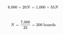
In this illustrative example, the costs are equal at 200 boards. Above that quantity, wave soldering has a lower calculated cost; below it, hand soldering has a lower calculated cost. Real results can differ substantially because labour, setup, throughput and defect costs vary by plant.
What should you compare before choosing?
Calculate cost per accepted board, not just cost per board processed. Record actual production time, solder consumption, dross, rejected joints, rework, maintenance and changeover time for both processes. For a high-volume production line, a controlled pilot run is more useful than relying on generic industry averages.
Internal linking opportunity: Link “solder wire material” to the most relevant solder wire or material-selection page. Keep this cost section focused on process economics; avoid linking it to a product page using repeated commercial keywords in every paragraph.
Mixed-Technology Boards: Combining Processes
Mixed-technology boards often combine wave soldering for suitable through-hole components with hand soldering for local joints, rework or components that cannot safely pass through the wave process. The best sequence depends on component placement, thermal sensitivity, board design, masking requirements and production volume. Define the process route in advance and validate the combined sequence to avoid damaging previously completed joints.
Why do mixed-technology boards need more planning?
A mixed-technology PCB may contain surface-mount devices (SMDs), through-hole components, connectors and parts with different thermal limits. One process may not be suitable for every joint on the board.
Wave soldering can efficiently process suitable through-hole connections, but components on the underside, fine-pitch parts or heat-sensitive components may require special consideration. Hand soldering can address selected joints, but it introduces operator-dependent variation and can increase production time when used extensively.
How should the process sequence be planned?
- Review the PCB design. Identify through-hole components, surface-mount parts, connector locations, clearances and areas exposed to the solder wave.
- Check component thermal limits. Confirm that the planned process will not exceed approved temperature or exposure limits.
- Choose the primary process. Use wave soldering for suitable high-volume through-hole joints when the board design supports it.
- Identify joints requiring manual work. Reserve hand soldering for suitable exceptions, rework and locations inaccessible to the wave process.
- Plan masking and protection. Where required, use approved fixtures, pallets or masking methods to protect components and surfaces.
- Validate the order of operations. Check whether later heating could disturb earlier joints, damage components or affect flux residues.
- Inspect and test the completed board. Use the acceptance criteria and electrical tests specified for the product.
How does solder material selection change?
Wave soldering requires a suitable solder-pot alloy and a flux system compatible with the process. Hand soldering normally requires solder wire with an appropriate alloy, diameter and flux arrangement. The alloys do not have to be identical in every application, but any differences must be assessed for compatibility with the assembly specification and customer requirements.
For example, a production line may use a lead-free alloy in the wave pot while operators use a compatible lead-free solder wire for manual work. That is not a universal rule: the approved material specification, existing joints and product requirements determine the correct choice.
Storage and Handling in Indian Conditions
Solder wire, flux and solder alloys should be stored in clean, dry conditions, protected from contamination, physical damage and unsuitable temperature or humidity exposure. Indian conditions vary significantly between humid coastal regions, monsoon periods and dry inland locations, so storage controls should reflect the product’s technical data sheet and packaging instructions. Keep materials identifiable, sealed when appropriate and traceable to their batch documentation.
What storage conditions should manufacturers maintain?
Solder materials can be affected by contamination, damaged packaging, oxidation of exposed surfaces and improper handling. Flux-containing products may have additional storage or shelf-life requirements depending on their chemistry and packaging.
For Indian facilities, practical controls include:
- Humidity and moisture: Monitor storage conditions where moisture-sensitive materials or packaging require it. Do not assume every solder wire needs the same humidity limit.
- Temperature: Follow the manufacturer’s stated storage range and avoid uncontrolled exposure to heat.
- Clean storage: Keep materials away from dust, oil, chemicals, water and other sources of contamination.
- Original packaging: Retain labels and packaging where possible to protect the product and preserve batch information.
- Stock rotation: Apply FIFO (first in, first out) or the manufacturer’s specified shelf-life control where applicable.
- Batch traceability: Record the product grade, alloy, batch number, receipt date and relevant certificates.
- Flux-specific instructions: Follow the technical data sheet for flux-cored solder wire and separately supplied fluxes.
Does monsoon humidity automatically damage solder wire?
It doesn’t have to be so. The level of risk will vary according to the make-up of the product, the type of packaging, the length of time it has been exposed, the state of the surface, and the instructions for storage given by the manufacturer. Simply having high humidity does not mean that a material has become unsuitable, and a mere visual examination might not be enough to prove that it is still fit for use.
When the packaging is damaged, the material is found to be contaminated or the solderability is in question, the batch should be separated and the supplier’s inspection or requalification procedure should be followed before it is released for production. Improvised drying or heating methods should not be used unless the manufacturer specifically approves them.
How should solder wire be handled on the production floor?
Make sure that the wire spools are kept clearly labelled and are protected when not in use. Do not handle the soldering surfaces unless necessary, do not mix together batches that have not been identified, and avoid placing the wire in a position where it can pick up oil and dust. It is important that the operators understand the difference between alloy identity, flux type and wire diameter since these properties have an effect on various aspects of the soldering process.
When looking at Kothari Metsol’s product documentation for the relevant material, it should be read together with the actual purchase specification and the process requirements. If there is anything unclear regarding storage limits, shelf life or material identification, you should ask the supplier for clarification.
Safety and Environmental Notes
When carrying out wave soldering or hand soldering, it is necessary to have in place measures for the hazards of hot surfaces, molten metal, flux fumes, splashes and when handling materials. Wave soldering involves additional risks due to the use of a molten solder bath and the moving equipment, whereas hand soldering causes operators to be exposed to hot tips and to local fumes. Appropriate ventilation, personal protective equipment, training and documented procedures should be used, these being based on the materials and hazards involved.
What safety measures apply to both processes?
- Provide suitable local exhaust ventilation for soldering fumes, following the risk assessment and applicable workplace requirements.
- Use eye protection and other PPE appropriate to the task and risk assessment.
- Keep hands and work surfaces clean, and follow hygiene procedures after handling solder or flux.
- Keep food and drink away from soldering and material-handling areas.
- Train operators to recognise hot surfaces, burns, splashes and equipment hazards.
- Follow the safety data sheet (SDS) for the solder alloy, flux and any cleaning chemicals.
- Keep spill response, first aid and emergency procedures accessible to staff.
What additional risks come with wave soldering?
Since wave soldering uses a bath of molten metal, any accidental contact or the presence of moisture in the bath can result in serious hazards. It is necessary to use approved methods for loading, together with machine guards and proper maintenance procedures. Do not put wet tools, components or materials into the molten solder, and do not carry out maintenance until the equipment has been placed in the required safe condition.
How should solder waste and residues be managed?
Separate the solder dross, the metal-containing waste, the used flux containers and the cleaning residues according to their composition and in accordance with the relevant waste management requirements. You should not assume that all solder waste can be thrown away with ordinary rubbish. Where necessary, arrange for its disposal or recovery with authorised service providers and keep records in accordance with the facility’s legal and environmental obligations.
When it comes to products and operations in India, you should check the rules that actually apply to the particular facility and waste stream rather than considering all solder waste as electronic waste. Although the Central Pollution Control Board offers official information about India’s E-Waste Management framework, whether or not the rules apply will depend on the type of waste and the relevant legal definitions.
What about lead-free solder?
While lead-free solder can reduce the use of lead in relevant manufacturing processes, its use does not automatically ensure that the entire electronic product meets all environmental requirements. When selecting materials it is necessary to adhere to the product specification, the applicable regulations and any pertinent exemptions. Leaded solder might still be allowed in some applications or on the basis of applicable exemptions, so it is important to check the actual requirements before altering a qualified process.
Final Checklist: Choosing the Right Process and Solder
Use wave soldering if the PCB design, the volume of production and the process requirements all allow for efficient and repeatable soldering of the appropriate joints; for prototypes, small volumes, individual joints and suitable rework situations, choose hand soldering. Before approving either method, it is necessary to check the solder alloy, the compatibility of the flux, the capability of the equipment, the cost per accepted board, the safety controls and the quality requirements. Make sure the decision is recorded so that the production teams can follow a consistent and validated procedure.
Process selection checklist
Use this checklist before approving a soldering process for production.
Production approval checklist
Board and production requirements
- Identify through-hole and surface-mount components.
- Confirm production volume, batch size and changeover frequency.
- Check component thermal limits, board clearances and accessibility.
Solder material
- Confirm the approved alloy and material specification.
- Check flux type and compatibility with the selected process.
- For hand soldering, select a suitable solder wire diameter and format.
- Verify supplier documentation, batch identification and traceability.
Process and quality
- Define operating parameters and approved process instructions.
- Assess inspection, electrical testing and rework requirements.
- Validate the process using representative boards before full production.
Cost, safety and environment
- Calculate cost per accepted board using actual plant data.
- Include setup, labour, consumables, maintenance and defect costs.
- Review ventilation, PPE, training and molten-metal hazards where relevant.
- Define procedures for dross, flux residues and other process waste.
When should you choose wave soldering?
Wave soldering should be considered if you have a stable and repeatable production run, suitable through-hole joints, and a sufficient volume to make it worthwhile in terms of the cost of setting up and operating the machinery. It is, however, necessary that the wave soldering process is compatible with both the PCB design and the components. Before deciding to go into production, you must confirm the approved alloy, flux system, equipment settings, maintenance requirements and inspection plan.
When should you choose hand soldering?
Hand soldering is frequently suitable for use in prototypes, small batches, repair work and cases where individual attention is required. It provides a degree of flexibility and calls for a relatively small initial outlay, but the results are influenced by the skill of the operator, the tools used, the choice of materials and the work instructions. When it comes to repeated production, it is necessary to set up uniform soldering methods and inspection standards so that quality does not rely completely on the individual technique.
How Kothari Metsol fits into solder material selection
When considering Kothari Metsol for use in connection with manufacturing requirements, buyers and engineers should first determine the intended process, the required alloy specification, the necessary flux characteristics, the wire diameter if relevant, and their documentation needs before asking for product recommendations. It is useful to compare the products with a written specification in order to make sure that the material selected is suitable for the actual application rather than basing the choice on a general product description.
Standards and technical references to consult
When carrying out the assembly of electronics, it is necessary to examine the standards set out by your customer, the product design authority or the quality system.
IPC has designated J-STD-001 as the standard that covers the requirements for soldered electrical and electronic assemblies, namely those relating to materials and the manufacturing processes, and IPC-A-610 looks at the acceptability after assembly.
For each project it is essential to verify the relevant revision, the product class and the contractual requirements.
The references are for the purpose of technical review and do not take the place of your approved manufacturing instructions, safety data sheets or customer-specific requirements.
Frequently Asked Questions
1. What is the main difference between wave soldering and hand soldering?
Wave soldering involves the use of a regulated wave of molten solder to join appropriate PCB connections and is widely used on production lines, while hand soldering makes individual joints by means of a heated tool and solder wire. The principal differences lie in the method of material delivery, the equipment employed, the volume of production, the degree of process control, and suitability for particular applications.
2. Does wave soldering use solder wire?
Soldering by the wave method usually involves using a solder alloy that is kept in a molten bath rather than feeding solder wire directly to each joint. Flux is typically applied separately prior to the board getting to the wave. The alloy and the flux must be compatible with the PCB, the requirements of the components, and the approved manufacturing process.
3. Which solder wire is best for hand soldering?
The solder wire that should be used will depend on the alloy specified, the type of flux core, the diameter of the wire, the size of the joint, and the application requirements. You should choose a product which corresponds to the assembly specifications and the residue requirements. There is not a single solder wire that is best for every component, every PCB or every soldering task.
4. Can lead-free solder be used for both wave and hand soldering?
Lead-free alloys may be used in both processes provided that the chosen alloy, flux system, equipment and process parameters are appropriate. Yet the entire material setup is not automatically compatible. It is necessary to verify the approved alloy, the operating conditions, the component limits and the quality requirements before using it in either process.
5. Is wave soldering better than hand soldering for PCB assembly?
Wave soldering is more efficient when it comes to the repeated production of compatible PCB assemblies, in particular in the case of those which have a large number of suitable through-hole joints. For prototypes, repairs and individual connections, hand soldering is generally more practical. The most appropriate method will vary according to the board’s design, the volume of production, the equipment available, the quality requirements and the total cost.
6. What causes defects during wave and hand soldering?
Faults may be caused by the use of inappropriate materials, poor surface preparation, wrong temperatures, insufficient flux activity, equipment troubles or an inconsistent technique. In the case of wave soldering, bridging or a lack of solder may occur, whereas with hand soldering cold joints or too much solder might result. The appropriate action is to examine the process and check the cause.
7. How do I choose the correct solder material for an industrial application?
Begin by referring to the assembly specification, the required alloy, the process type, the component finishes and any applicable regulatory or customer requirements. Next, check the flux compatibility, the material dimensions or the bath requirements, the documentation and the quality criteria. Finally, cross-check the chosen option against the approved manufacturing process rather than making your choice on the basis of price alone.